250cc 6 Pin Cdi Wiring Diagram
The CDI (Capacitor Discharge Ignition) system is a vital component in the operation of many small engines, including motorcycles, ATVs, and scooters. With the right wiring connections, the CDI box controls the ignition timing, spark intensity, and overall engine performance.

⭐ 6 Pin Cdi Wiring Diagram Ac ⭐ Great deal seureka superlite vacuum
Looking to wire up your motorcycle CDI? In this video, we walk through a basic 5 pin CDI wiring diagram. We explain how each pin on the CDI unit connects and.
6 Pin Cdi Wiring Diagram Wiring Diagram
The good news is that by learning how CDI systems work and using the correct 5 pin CDI wiring diagram for your particular model, you can diagnose and fix ignition issues on your own and get your wheels back on the road. In this complete guide, you'll learn: How 5 pin CDI ignition systems work The purpose of each wire in a CDI wiring harness
Cdi Wiring Diagram Atv
A Bajaj CDI Unit Wiring Diagram is an essential tool for complicated electrical systems, such as on a motorbike. This diagram enables technicians to quickly identify any wiring problems and make the necessary repairs in a timely manner. With a comprehensive wiring diagram, it is possible to pinpoint any issue with the wiring without having to.

[DIAGRAM] 5 Pin Cdi Wiring Diagram Suzuki
The new racing CDI box wiring diagram consists of a visual representation of how each wire should be connected to the CDI box and other related components. It also includes an organized list of the various components used in the wiring system and their specific locations.. 5 Pin Racing Cdi Box Ignition Coil For Motorcycle 50cc 70cc 90cc.

Chinese Motorcycle Cdi Wiring Diagrams Images Funart
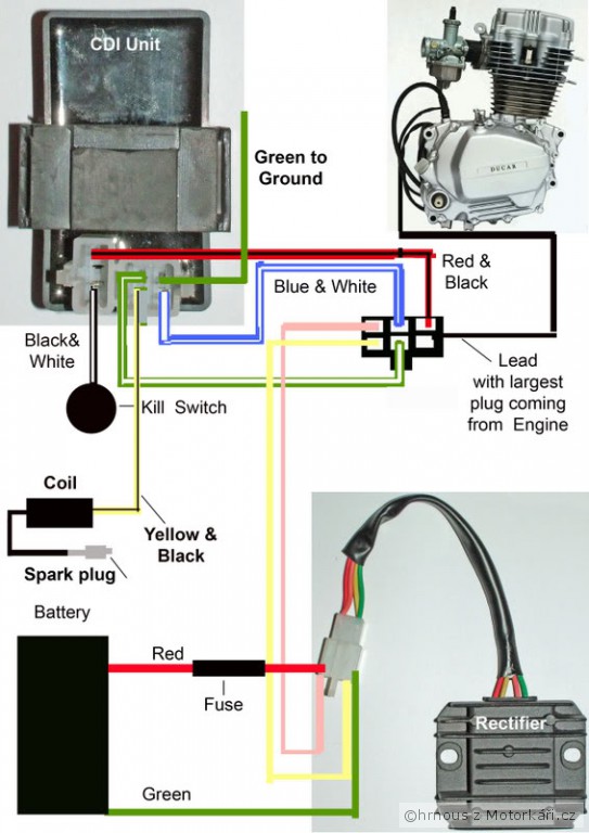
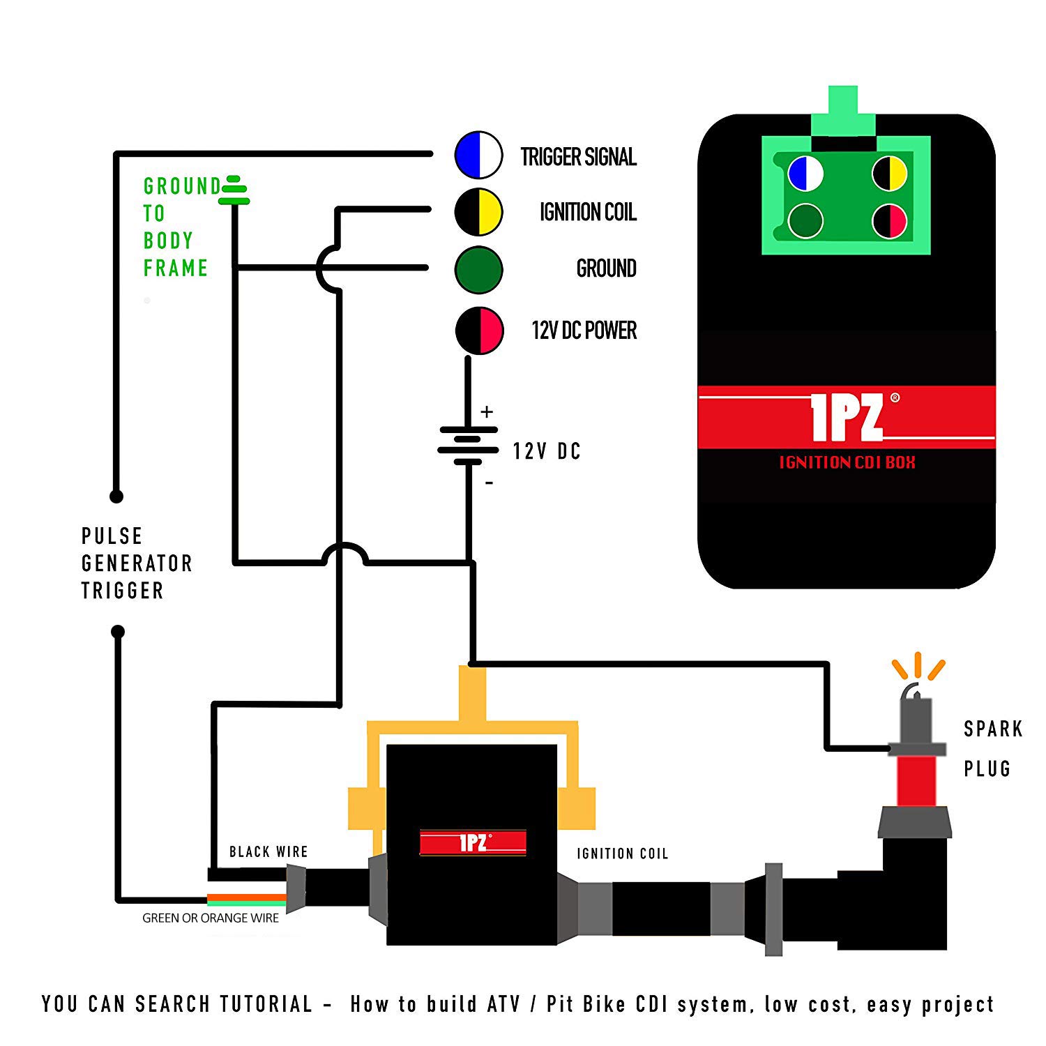
The five pins connect to the following components to provide power to the engine: Timing trigger (or pulse generator) Ignition coil CDI ignition power
Yamaha 8 Pin Cdi Wiring Diagram down to earth blog
Once the Honda CDI box is connected, the wiring diagram will also provide details on how to properly connect the box to the vehicle's electrical system. This includes connecting it to the battery, the ground and the starter relay, among others. Additionally, different types of connectors are used when connecting the box to the vehicle's.
Atv Cdi Wiring Diagrams
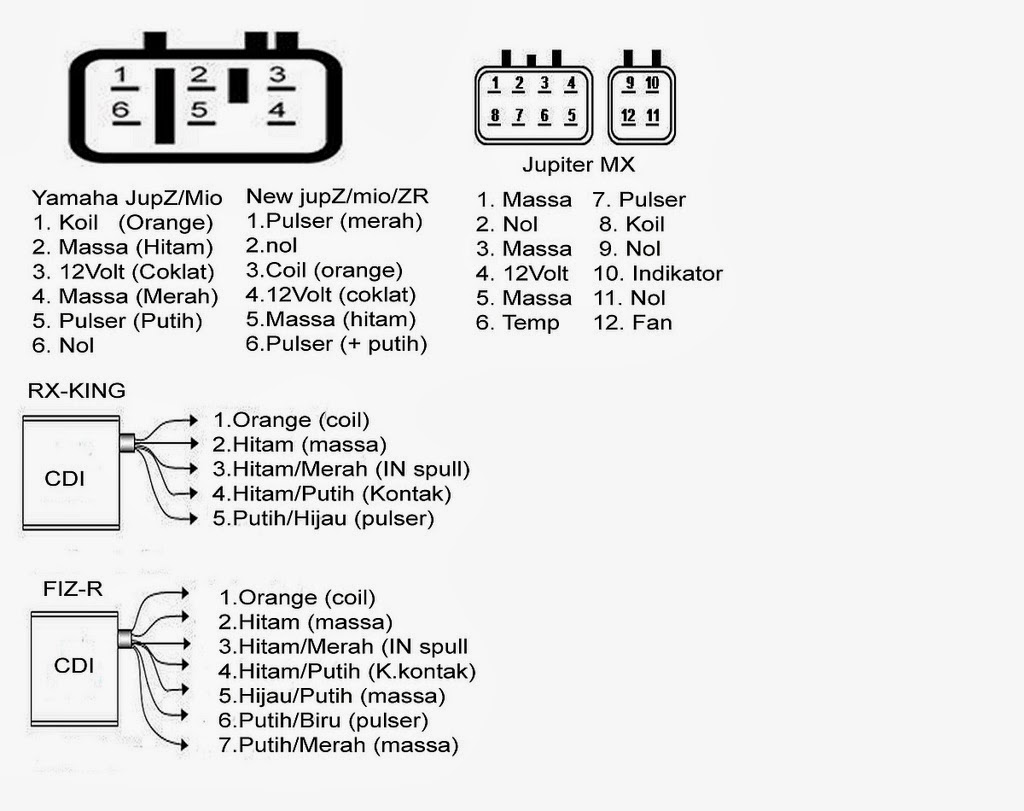
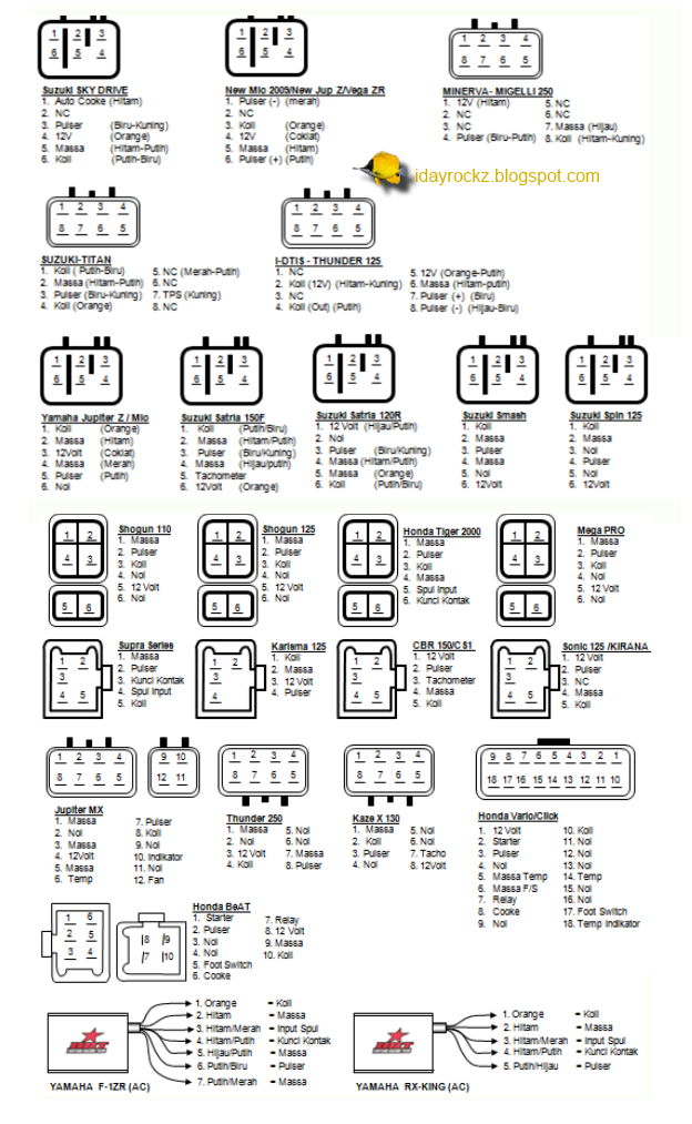
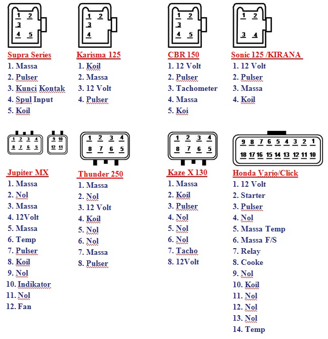
Yamaha 8 pin CDI wiring diagrams are the key to understanding how your CDI system works. The diagrams are usually printed on the CDI itself, or on the engine's wiring harness. They show the connections between each component and how they interact with each other. The diagrams can be confusing to read, but with a little patience and some.
Bestly Cdi Ignition Coil Wiring Diagram
Six Tips for electric wiring. 1. Power Tests. Check & test wires and devices with regard to power inside the box you usually are working in to stop electric shock just before working on them. Sometimes, even when you shut off power, some cabling may be connected to another circuit & hence may still pose a danger of electric surprise. 2.

High Gain Dual Band Antenna Wifi high [51+] Honda 8 Pin Cdi Wiring
That's the site I've been using and they show a newer cdi box (21119-1415) or (21119-0010), while I have the (21119-1229). I have the newer wiring harness but I don't have a newer cdi box, ignition switch. 1. r/Kawasaki.

[DIAGRAM] 5 Pin Cdi Wiring Diagram Suzuki
This diagram shows you exactly how to wire a 5-pin CDI. Each wire is labeled and color-coded, making it easy to identify and connect the correct wires. The diagram also includes additional information and tips to help you troubleshoot any issues you may encounter along the way.
Gambar Skema Rangkaian Cdi Shogun 110 Skema Diagram
Skip the cable setup & start watching YouTube TV today - for free. Then save $22/month for 3 months. Wiring a CDI and the differance between AC/DC units.
7 pin cdi wiring diagram
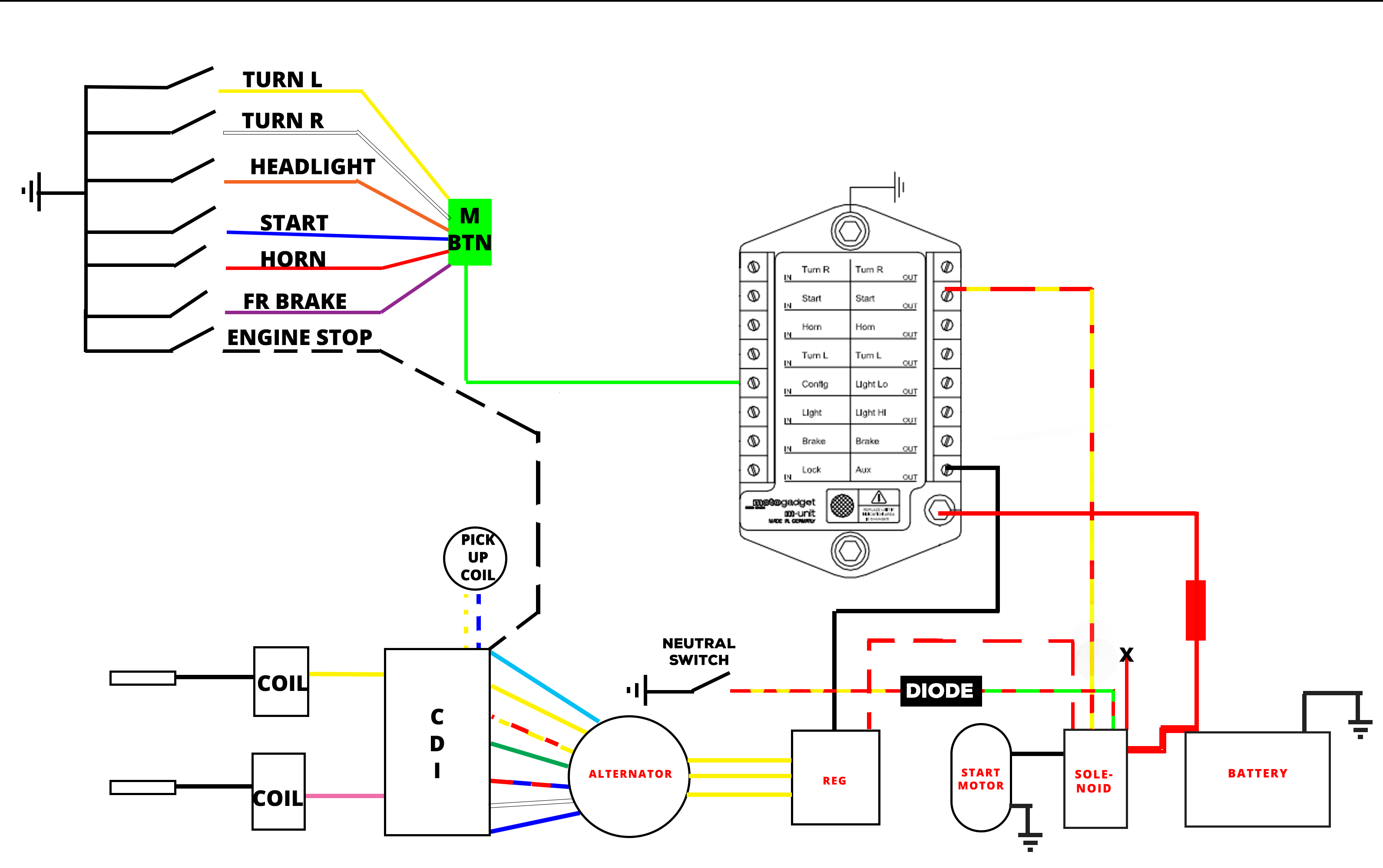
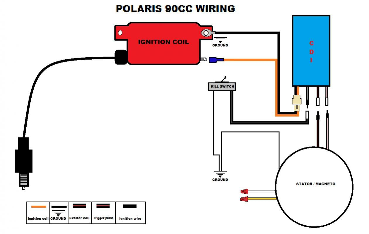
How The CDI Works III. 6 Pin CDI Box IV. AC CDI Box or DC CDI Box - 6 Pin AC CDI Box - 6 Pin DC CDI Box V. Connecting The CDI Box - CDI Ignition Power - Ignition Coil - Timing Trigger - Kill Switch Or Ignition Key Switch - Ground Wires VI. 6 Pin AC CDI Wiring Diagram VII. 6 Pin DC CDI Wiring Diagram VIII. Conclusion CDI System
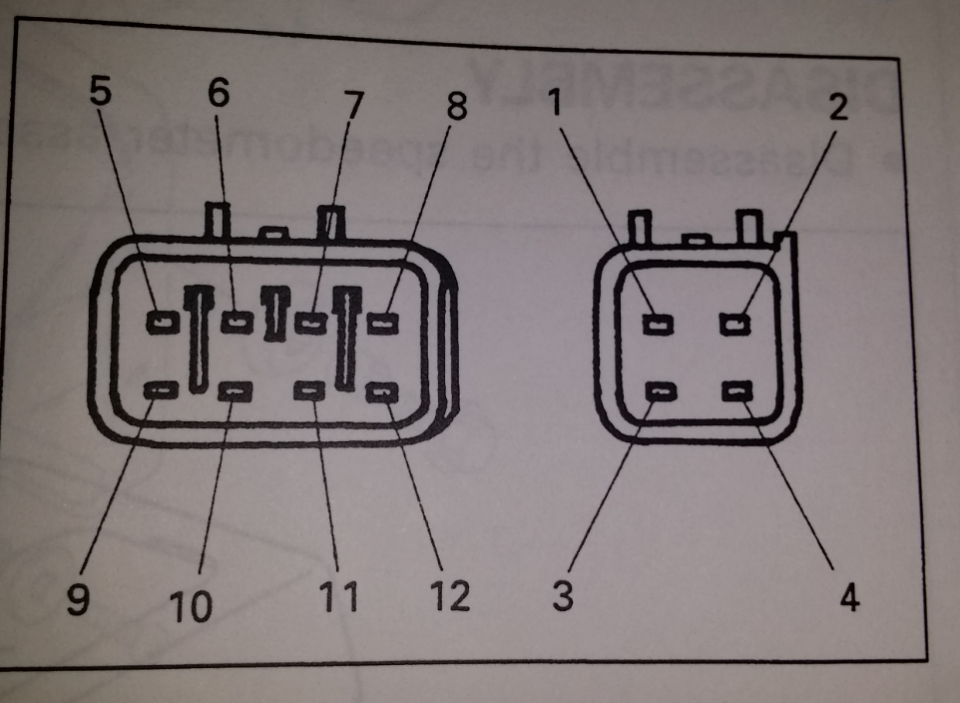
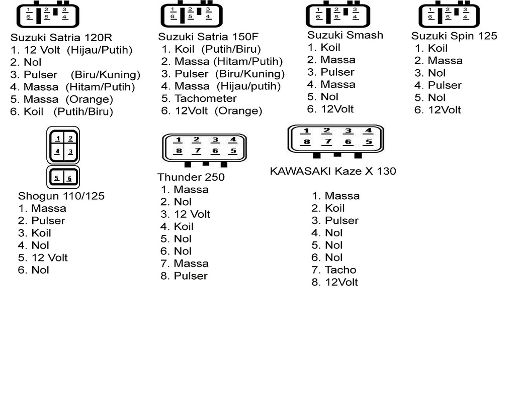
Connection pin CDI Motor Cycle
About Press Copyright Contact us Creators Advertise Developers Terms Privacy Policy & Safety How YouTube works Test new features NFL Sunday Ticket Press Copyright.
2 Stroke Cdi Wiring Diagram
Bike: TZR pit bike. Re: 5 Wire system loom / How to wire it up, Need help please. Looks straight forward enough, the CDi has 6 pin locations, but only 4 or 5 pins used. If you use the blue/white wire and connect it to pin 1 in the image below. red/black wire to pin 3, the other wires are obvious. The yellow or white wires are for lighting, so.
2 pin cdi wiring diagram
The wiring diagram provides a visual representation of how these pins should be connected, ensuring a reliable and functional ignition system. In conclusion, a 12 pin CDI wiring diagram is a valuable resource for anyone working with a CDI unit.